- 您现在的位置:买卖IC网 > Sheet目录1993 > DS1181LE+ (Maxim Integrated Products)IC CLOCK MOD SS 8-TSSOP
ABSOLUTE MAXIMUM RATINGS
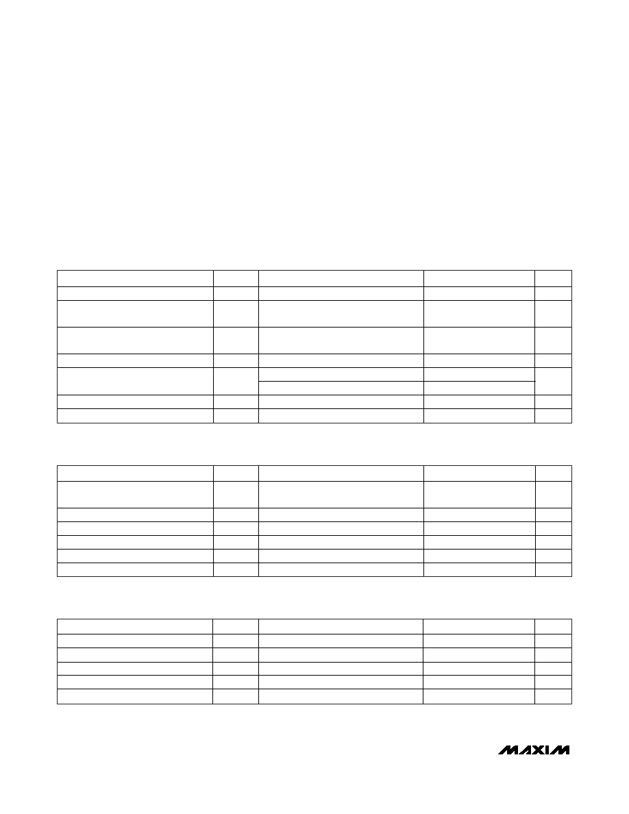
RECOMMENDED OPERATING CONDITIONS
(TA = -40°C to +125°C, unless otherwise noted.)
Stresses beyond those listed under “Absolute Maximum Ratings” may cause permanent damage to the device. These are stress ratings only, and functional
operation of the device at these or any other conditions beyond those indicated in the operational sections of the specifications is not implied. Exposure to
absolute maximum rating conditions for extended periods may affect device reliability.
Voltage Range on VCC Relative to GND ...............-0.5V to +4.3V
Voltage Range on Any Lead Relative
to GND ..................-0.5V to (VCC + 0.5V), not to exceed +4.3V
Operating Temperature Range .........................-40°C to +125°C
Storage Temperature Range .............................-55°C to +125°C
Soldering Temperature...................See J-STD-020 Specification
PARAMETER
SYMBOL
CONDITIONS
MIN
TYP
MAX
UNITS
Supply Voltage
VCC
(Note 1)
3.0
3.6
V
Input Logic 1
VIH
0.8 x
VCC
VCC +
0.3
V
Input Logic 0
VIL
-0.3
0.2 x
VCC
V
Input Logic Float (SSEN, CRSEL)
IFLOAT
0V < VIN < VCC
±1
μA
SSO < 80MHz
15
SSO Load
CL
80MHz
SSO < 134MHz
7
pF
CLKIN Frequency
fIN
20
134
MHz
CLKIN Duty Cycle
fINDC
40
60
%
DC ELECTRICAL CHARACTERISTICS
(VCC = +3.0V to +3.6V, TA = -40°C to +125°C, unless otherwise noted.)
PARAMETER
SYMBOL
CONDITIONS
MIN
TYP
MAX
UNITS
Supply Current
ICC
CL = 7pF,
fIN = 134MHz
18
mA
SMSEL1/SMSEL2/CLKIN Input Leakage
IIL:1
0V < VIN < VCC
-1
+1
μA
CRSEL/SSEN Input Leakage
IIL:2
0V < VIN < VCC
-100
+100
μA
Output Leakage (SSO)
IOZ
SSEN = float
-1
+1
μA
Low-Level Output Voltage (SSO)
VOL
IOL = 4mA
0.4
V
High-Level Output Voltage (SSO)
VOH
IOH = -4mA
2.4
V
AC ELECTRICAL CHARACTERISTICS
(VCC = +3.0V to +3.6V, TA = -40°C to +125°C, unless otherwise noted.)
PARAMETER
SYMBOL
CONDITIONS
MIN
TYP
MAX
UNITS
SSO Duty Cycle
fSSODC
Measured at VCC/2
40
60
%
SSO Rise Time
tR
CL = 7pF
1
ns
SSO Fall Time
tF
CL = 7pF
1
ns
Peak Cycle-to-Cycle Jitter
tJ
TA = -40°C to +85°C, 10,000 cycles
75
ps
Power-Up Time
tPOR
(Note 2)
50
ms
DS1181L
20MHz to 134MHz Spread-Spectrum
Clock Modulator for LCD Panels
2
_______________________________________________________________________________________
Note 1: All voltages referenced to ground. Currents into the IC are positive and out of the IC are negative.
Note 2: Time between power applied to device and stable output.
发布紧急采购,3分钟左右您将得到回复。
相关PDF资料
DS1243Y-120
IC NVSRAM 64KBIT 120NS 28DIP
DS1244W-120IND
IC NVSRAM 256KBIT 120NS 28DIP
DS1248Y-70IND
IC NVSRAM 1MBIT 70NS 32DIP
DS1251WP-120+C02
IC NVSRAM 34PWRCP
DS1254WB-150
IC NVSRAM 16MBIT 150NS 168BGA
DS1286I+
IC TIMEKEEPER WATCHDOG 28-EDIP
DS12885T
IC RTC W/RAM 128 BYTE 32-TQFP
DS12C887A+
IC RTC W/RAM 128 BYTE 24-EDIP
相关代理商/技术参数
DS1181LE+T
功能描述:时钟发生器及支持产品 Spread-Spectrum CLK Mod for LCD Panels RoHS:否 制造商:Silicon Labs 类型:Clock Generators 最大输入频率:14.318 MHz 最大输出频率:166 MHz 输出端数量:16 占空比 - 最大:55 % 工作电源电压:3.3 V 工作电源电流:1 mA 最大工作温度:+ 85 C 安装风格:SMD/SMT 封装 / 箱体:QFN-56
DS1182
制造商:OSRAM 功能描述:LAMP DULUX WARM 11W
DS1184
制造商:OSRAM 功能描述:LAMP DULUX S COOL 11W 制造商:OSRAM 功能描述:LAMP, DULUX, S, COOL, 11W 制造商:OSRAM 功能描述:LAMP, DULUX, S, COOL, 11W; Supply Voltage:91V; Lamp Base Type:2 Pin; Power Rating:11W; Luminous Flux:900lm; Length:237mm; Bulb Diameter:19.5mm; Colour Temperature Typ:4000K; SVHC:No SVHC (19-Dec-2012); Average Bulb Life:8000h; ;RoHS Compliant: Yes 制造商:OSRAM 功能描述:LAMP, DULUX, S, COOL, 11W ;ROHS COMPLIANT: YES
DS-11880
制造商:未知厂家 制造商全称:未知厂家 功能描述:Power Dividers Space Qualified
DS119
制造商:Cooper Tools / Weller 功能描述:Bulk
DS119
制造商:Cooper Hand Tools / Weller 功能描述:DRILL BIT SAUGNADEL SMD 制造商:WELLER 功能描述:DRILL BIT, SAUGNADEL, SMD
DS1190N+
功能描述:可编程振荡器 3/5V Prog Ramping Oscillator RoHS:否 制造商:IDT 封装 / 箱体:5 mm x 7 mm x 1.5 mm 频率:15.476 MHz to 866.67, 975 MHz to 1300 MHz 频率稳定性:+/- 50 PPM 电源电压:3.63 V 负载电容:10 pF 端接类型:SMD/SMT 输出格式:LVPECL 最小工作温度:- 40 C 最大工作温度:+ 85 C 尺寸:7 mm W x 5 mm L x 1.5 mm H 封装:
DS1190N+T
功能描述:可编程振荡器 3/5V Prog Ramping Oscillator RoHS:否 制造商:IDT 封装 / 箱体:5 mm x 7 mm x 1.5 mm 频率:15.476 MHz to 866.67, 975 MHz to 1300 MHz 频率稳定性:+/- 50 PPM 电源电压:3.63 V 负载电容:10 pF 端接类型:SMD/SMT 输出格式:LVPECL 最小工作温度:- 40 C 最大工作温度:+ 85 C 尺寸:7 mm W x 5 mm L x 1.5 mm H 封装: